Thursday, March 24, 2011

How To Upgrade vSphere 4.1 Update 1

With VMware vSphere 4.1 update 1 now generally available, what do you need to know about it and how do you upgrade to it? Let's find out.

With VMware vSphere 4.1 update 1 now generally available, what do you need to know about it and how do you upgrade to it? Let's find out.
The new vSphere 4.1 Update 1 includes updates to vCenter, ESX Server, and ESXi Server.
The new features in ESX Server 4.1 U1 are:
  • Support for up to 160 logical processors
  • Support for additional guest operating systems: RHEL 6, RHEL 5.6, SLES 11 SP1 for VMware, Ubuntu 10.10, and Solaris 10 Update 9
  • Support for additional drivers
  • Resolution of a number of issues (bugs)
The new features in vCenter 4.1 U1 are:
  • Customization of additional operating systems - Windows 7 SP1 (x32 and x64), Windows Server 2008 R2 SP1 (x32 and x64), RHEL 6.0 (x32 and x64), RHEL5.5 (x32 and x64)
  • Additional vCenter database support - Microsoft SQL Server 2008 R2, Microsoft SQL Server 2005 SP3, Oracle 11g Standard/Enterprise Release 2, 11.2.0.1.0 or later, (x32 and x64), IBM DB2 9.7.2 Express C (x32 and x64), IBM DB2 9.7.2 Enterprise (x32 and x64)
  • Resolution of a number of issues (bugs)
Unless you require the new OS or database support or need a bug fixed that it fixes, update 1 isn't required. However, what interests most in this update is the number of issues (bugs) that are resolved (fixed) in this release. You never know when your virtual infrastructure could be affected by one of those issues so (hopefully) you would be better off by keeping current.
To move to the latest ESX or ESXi Server platform host, I recommend the following steps:
  1. Read the vSphere 4.1 Update 1 release notes for ESX Server and vCenter.
  2. Download vSphere 4.1 Update 1 from the VMware vSphere 4 Download site (notice the 2011/02/10 dates on the update 1 code; see Fig. 1).
Downloading Update 1 from VMware's Download site.
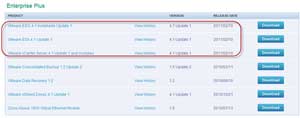
Figure 1. Downloading Update 1 from VMware's Download site. (Click image to view larger version.)
  1. Upgrade vCenter using either the ISO file or the ZIP file the Windows installable (see Fig. 2). I recommend backing up vCenter (and its associated database) before the upgrade. If your vCenter server is running as a VM, the easiest way to protect yourself is to do a snapshot.
Upgrading via the ISO file
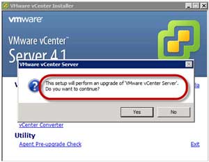
Figure 2. Upgrading via the ISO file. (Click image to view larger version.)
  1. Upgrade the vSphere Client using the Windows installable.
  2. Upgrade Update Manager, if you are using it.
  3. Upgrade ESX Server using one of the three options below. You could prevent downtime for VMs (and end users) during the upgrade by using VMotion and to migrate VMs to another ESX host until the upgrade is completed:
    • Use vCenter Update Manager (VUM) to upgrade ESX & ESXi Server. VUM is the easiest & recommended way to upgrade your VMware infrastructure. If you already have VUM then, likely, you already know how to use it.
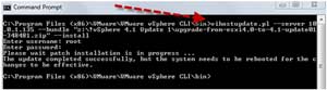
    • OR, use the CLI options - esxupdate for ESX Server and vihostupdate for ESXi. Here is an upgrade I did to update 1 on an ESXi 4.1 host using vCLI and the ZIP version of the update 1 install (see Fig. 3).

      upgrade via update 1 on an ESXi 4.1 host using vCLI and the ZIP version of the update 1 install
      Figure 3. An upgrade via update 1 on an ESXi 4.1 host using vCLI and the ZIP version of the update 1 install. (Click image to view larger version.)

    • OR, burn 4.1 update 1 on a CD and upgrade the host by using a CD-based install (watch out on this method as it could be tricky or impossible to preserve your host configurations).
  4. Upgrade VMware Tools on each of the virtual machines. You could, of course, do this manually or use VUM to do it.
Once your upgrades to 4.1 update 1 are completed, you should see that your vCenter, ESX, and ESXi Servers have all changed from version 4.1.0 build 260247 to 4.1.0 build 348481 (see Fig. 4).
Version numbers have changed
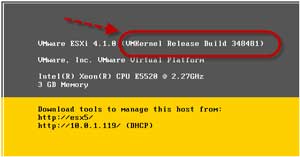
Figure 4. Version numbers have changed... (Click image to view larger version.) 
For more detailed information and specific upgrade scenarios, consult the VMware vSphere Upgrade Guide and VMware KB 1022140
Keeping current on new releases isn't always fun and may not always seem immediately beneficial. How quickly to update critical infrastructure software like vSphere is always up for debate. On one hand, there could be a bug in a new release that causes downtime. On the other hand, the long list of bug fixes in the new release could prevent downtime if you were to be affected by one of them.
As for vSphere 4.1 Update 1, I recommend that you at least get started testing it in your lab to be prepared to update your infrastructure should it prove stable.

Wednesday, March 23, 2011

Lync 2010 v/s OCS 2007

What is different in Lync Server 2010
OCS 2007 / 2007 R2 Lync Server 2010
Virtualization not supported accepts some roles. Every role can be either virtual or physical.
A/V conferencing service cannot work separate. A/V conferencing service can run in a standalone server role which we can call A/V Conferencing Server.
No specific limits for A/V conferencing pool. If site has more than 10,000 users, we recommend that you deploy a separate A/V Conferencing pool.
No Survivable Branch Appliance. Survivable Branch Appliance, which is a new device introduced in Lync Server 2010.
Mediation role cannot be collocated with FE. Collocation of mediation with FE is recommended if you are not using SIP trunking or Direct SIP.
No Topology Builder. Lync 2010 giving you the opportunity to create your own topology for deployment.
No Central Management Store kind of thing. In Microsoft Lync Server 2010, configuration data about servers and services is moved to the Central Management store. Read-only copies of the data are replicated to all servers in the topology, including Edge Servers and survivable branch appliances
No Management Shell accept LCSCMD command. The Lync Server 2010 Management Shell is a new method of administration and management.
No Role base access control. Lync introduces role-based access control (RBAC). Lync Server 2010 includes 11 predefined roles that cover many common administrative tasks, also you can create custom roles.
MMC for Administration. Administration console is no longer using MMC, Lync Server Control Panel replaces the MMC administrative interfaces
No load balancing for SIP traffic. The Lync Server 2010 introduces DNS load balancing for SIP and media traffic (you will still need hardware LB for other traffic such as HTTP however this is the easiest part in configuring a HW load balancer)
Edge Server is separate and in DMZ. You manage Edge Servers from the internal network. All configuration data for servers and services resides in the Central Management database, which you can manage by using internal administrative tools.
No Support for hosted Exchange UM. Lync Server 2010 introduces support for integration with hosted Exchange UM.
No Support for Enhanced 9-1-1. Lync supports Enhanced 9-1-1 (E9-1-1) as part of your Enterprise Voice deployment.
1 Mediation means 1 Gateway. New for the Mediation Server in Microsoft Lync Server 2010 is the ability for a single Mediation Server to route outbound calls through multiple gateways.
No separate pool for Mediation. Lync Server 2010 has the ability for a Mediation Server to be deployed as a pool; this pool can be collocated with the Front End pool, or can be a standalone pool.
MOC cannot be updated through WSUS. Lync client can be updated through WSUS.
No support for Analog devices. Lync Server 2010 provides support for analog devices. Specifically, the supported analog devices are analog audio phone and analog fax machines. Now you can configure the analog gateways and devices in your organization to use Lync Server 2010.


Tuesday, March 22, 2011

How-TO: Configure DHCP on a CISCO router

This post is about configuring a CISCO router to act as a DHCP server in your network.
Task1: Configure R1 to act as a DHCP server and provide all network information to hosts in the LAN dynamically. (R1 and R2 are directly connected via Ethernet)
Server Configuration (R1)
!– enable dhcp server (default) service dhcp
! — defining DHCP pool with all network information
ip dhcp pool OFFICE
network 192.168.12.0 255.255.255.0
domain-name networkers-online.com
default-router 192.168.12.1 !– gateway address
dns-server 192.168.12.100 192.168.12.101 !– DNS servers
netbios-name-server 192.168.12.99 !– WINS servers
lease 2 !– lease time
!– defining static binding to R2 using its client-id
ip dhcp pool STATIC
host 192.168.12.2 255.255.255.0
client-identifier 01cc.010d.f000.00
!– exclude server and static addresses from the dynamic pool
ip dhcp excluded-address 192.168.12.1
ip dhcp excluded-address 192.168.12.100 192.168.12.101
ip dhcp excluded-address 192.168.12.200
p dhcp excluded-address 192.168.12.2
Client Configuration:
interface FastEthernet0/0
ip address dhcp client-id FastEthernet0/0
Troubleshooting and verfication:
IP address is assigned dynamically to R2
!– R2 f0/0 address is assigned via DHCP R2(config-if)#do sh ip int b
Interface IP-Address OK? Method Status Protocol
FastEthernet0/0 192.168.12.2 YES DHCP up up
!– R1 bindings has R2 as a static entry
R1#sh ip dhcp binding
Bindings from all pools not associated with VRF:
IP address Client-ID/ Lease expiration Type
Hardware address/
User name
192.168.12.2 01cc.010d.f000.00 Infinite Manual
R2 gets its domain-name dynamically from R1
R2#sh ip domain
networkers-online.com
R2 sets R1 as a default gateway using a floating static route
R2#sh ip route
Codes: C – connected, S – static, R – RIP, M – mobile, B – BGP
D – EIGRP, EX – EIGRP external, O – OSPF, IA – OSPF inter area
N1 – OSPF NSSA external type 1, N2 – OSPF NSSA external type 2
E1 – OSPF external type 1, E2 – OSPF external type 2
i – IS-IS, su – IS-IS summary, L1 – IS-IS level-1, L2 – IS-IS level-2
ia – IS-IS inter area, * – candidate default, U – per-user static route
o – ODR, P – periodic downloaded static routeGateway of last resort is 192.168.12.1 to network 0.0.0.0 C 192.168.12.0/24 is directly connected, FastEthernet0/0
2.0.0.0/24 is subnetted, 1 subnets
C 2.2.2.0 is directly connected, Loopback0
S* 0.0.0.0/0 [254/0] via 192.168.12.1
R2 learns Primary and secondary DNS servers from R1
R2#ping xyz.comTranslating “yahoo.com”…domain server (192.168.12.100) (192.168.12.101)
% Unrecognized host or address, or protocol not running.
for more information on how to configure DHCP features consult the following link CISCO IOS DHCP Server

Unicast Reverse Path Forwarding-Tutorial

Unicast Reverse Path Forwarding is a small security feature
 
When configured on an interface, the router checks the incoming packet’s source address with its routing table. If the incoming packet’s source is reachable via the same interface it was received, the packet is allowed. URPF provides protection again spoofed packets with unverifiable source.
Though basically a single line command, URPF can be a little confusing when used with access-list feature if order of operation is not understood completely.
We’ll use this simple topology to demonstrate URFP


R1 and R2 are connected through frame-relay and an Ethernet connection.
We test our basic connectivity.

R2#ping 150.1.12.1
Type escape sequence to abort.
Sending 5, 100-byte ICMP Echos to 150.1.12.1, timeout is 2 seconds:
!!!!!
Success rate is 100 percent (5/5), round-trip min/avg/max = 44/93/192 ms
R1#ping 150.1.12.2
Type escape sequence to abort.
Sending 5, 100-byte ICMP Echos to 150.1.12.2, timeout is 2 seconds:
!!!!!
Success rate is 100 percent (5/5), round-trip min/avg/max = 28/45/84 ms
R1#ping 150.1.21.2
Type escape sequence to abort.
Sending 5, 100-byte ICMP Echos to 150.1.21.2, timeout is 2 seconds:
!!!!!
Success rate is 100 percent (5/5), round-trip min/avg/max = 8/54/100 ms

All right we have reachability on both Ethernet and frame relay interfaces.

In order to demonstrate URPF we use two static routes on R1 and R2.
R1 uses frame-relay to reach R2’s loop back (2.2.2.2/24) 
and 
R2 user Ethernet to reach R1’s Loopback (1.1.1.1/24)

R1(config)#ip route 2.2.2.0 255.255.255.0 150.1.12.2
R2(config)#ip route 1.1.1.0 255.255.255.0 150.1.21.1
 
Without URPF, we should be able to ping R2’s loopback from R1’s loopback.
R1#ping 2.2.2.2 source lo 0
Type escape sequence to abort.
Sending 5, 100-byte ICMP Echos to 2.2.2.2, timeout is 2 seconds:
Packet sent with a source address of 1.1.1.1
!!!!!
Success rate is 100 percent (5/5), round-trip min/avg/max = 24/48/80 ms
Now we enable URPF on frame-relay interface on R2.
Now when the incoming packet arrives at the frame interface, R2 checks the source address (1.1.1.1/24) in its routing table.
Since the interface used to reach this address is Ethernet0/0 , URPF checks fail and ping is not successful.
!
interface S1/0
ip address 150.1.12.2 255.255.255.0
ip verify unicast reverse-path
R1#ping 2.2.2.2 source lo 0
Type escape sequence to abort.
Sending 5, 100-byte ICMP Echos to 2.2.2.2, timeout is 2 seconds:
Packet sent with a source address of 1.1.1.1
…..
Success rate is 0 percent (0/5)
All right!
This was the most simple part.
Now we use URPF with an access-list.
Understanding URPF Order of Operation:
Here we have to understand the order of operations.
1) When packet arrives at the interface, URPF check is done. If the check is successful, the packet is transmitted, and ACL doesn’t come into play
2) If the check is failed, ACL is consulted. Traffic is allowed or denied based on ACL entries.
3) The thing to understand here is that an ACL with deny any any will not mean that all traffic is denied. It won’t come into play unless the URPF check is failed. If URPF check is successful all traffic is allowed. If it is failed then ACL is checked an traffic is allowed or denied based on the ACL.
R2:
!
interface Serial1/0
ip address 150.1.12.2 255.255.255.
ip verify unicast reverse-path 101
access-list 101 permit tcp any any
access-list 101 deny ip any any log-input
Here we are allowing the TCP traffic and denying all other traffic in ACL.
It means that a telnet sourced from the LoopBack 0 of R1 to LoopBack 0 of R2 will be successful, but all other traffic will be denied.
From R1:
R1#telnet 2.2.2.2 /source-interface loopback 0
Trying 2.2.2.2 … Open
Password required, but none set
[Connection to 2.2.2.2 closed by foreign host]
Success rate is 0 percent (0/5)
R1#ping 2.2.2.2 source lo 0
Type escape sequence to abort.
Sending 5, 100-byte ICMP Echos to 2.2.2.2, timeout is 2 seconds:
Packet sent with a source address of 1.1.1.1
…..
Success rate is 0 percent (0/5)
Below is the log generated by ACL.
*Mar 1 00:16:40.171: %SEC-6-IPACCESSLOGDP: list 101 denied icmp 1.1.1.1 (Serial1/0 ) -> 2.2.2.2 (0/0),
Now lets ping the loopback with source frame-relay interface.
R1#ping 2.2.2.2 source S1/0
Type escape sequence to abort.
Sending 5, 100-byte ICMP Echos to 2.2.2.2, timeout is 2 seconds:
Packet sent with a source address of 150.1.12.1
!!!!!
Success rate is 100 percent (5/5), round-trip min/avg/max = 24/48/80 ms
As you can see that though ACL is denying all ICMP traffic our ping is successful.
For the simple reason that ACL won’t be checked until URPF check is failed. And in the above case, it’s successful.
Now lets change the ACL.
Now our intention is to allow HTTP traffic between the loopbacks as well as ICMP traffic and deny all other traffic.

R2:
access-list 101 permit tcp any any eq www
access-list 101 permit icmp any any
access-list 101 deny ip any any log-input
We’ll be able to ping or telnet at port 80 but regular telnet will fail
R1#ping 2.2.2.2 source lo 0
Type escape sequence to abort.
Sending 5, 100-byte ICMP Echos to 2.2.2.2, timeout is 2 seconds:
Packet sent with a source address of 1.1.1.1
!!!!!
Success rate is 100 percent (5/5), round-trip min/avg/max = 16/57/80 ms
R1#telnet 2.2.2.2 80 /source-interface loopback 0
Trying 2.2.2.2, 80 … Open
R1#telnet 2.2.2.2 /source-interface loopback 0
Trying 2.2.2.2 …
% Connection timed out; remote host not responding
R2: (:Log)
*Mar 1 00:20:18.895: %SEC-6-IPACCESSLOGP: list 101 denied tcp 1.1.1.1(35617) (S
erial1/0 ) -> 2.2.2.2(23), 1 packet
Well thats about it for URPF.
In lab exam if the feature shows up, be careful, as it can break connectivity if routers have asymmetrical routing.
Asymmetrical routing is not a problem in LAB generally as long as we have connectivity, but with URPF enabled, asymmetrical routing will break connectivity.
In that case,we can either tune unicast routing table or use the access-list with URPF to allow for connectivity.

Top 10 Tips for Cisco Routers Configuration

There are few simple things that might help administrators in utilizing their time working with Cisco routers. I gathered the most important ten things, in my point of view, and wrote them down.

1. The best sequence of configuring a Cisco router, as I see it, is the following:
 
a. Setup the hostname with the ‘hostname XXXXXX’ command.
b. Setup the secret password (or enable password) with the ‘enable secret XXXXX’ command.
c. Setup console and telnet passwords (use the ‘logging synchronous’ command at the console) with the ‘password XXXXX’ and ‘login’ commands.
d. Encrypt the un-encrypted passwords with ‘service password-encryption’ command and don’t forget to turn it off after you ‘show run’.
e. Setup the interfaces (IP addresses, description, bandwidth, etc) with ‘ip address’, ‘bandwidth’, and ‘description’ commands
f. Setup the Routing protocols (or static routes)
g. Test the connectivity with ‘ping’ and ‘traceroute’
h. Setup the access-lists
i. Test the connectivity (again)
 
2. Be as descriptive as possible.
Use the ‘description’ command on ALL interfaces. And give useful description in it. Describe the network to which this interface is connected, the bandwidth of the link, the duplex settings, and any other information that you might think useful. Use ‘remark’ in writing the access-lists so you would identify the access-list according to its function. And if you find it necessary, use banners. 
Examples:
RouterA(config-if)#description This link is connected to the Accounting Lan
RouterA(config)#access-list 101 remark This list stops the telnet to the Marketing net
RouterA(config)#banner motd #This router is connected to the marketing and accounting LANS#

3. Use hotkeys.
There are many useful hotkeys in the configuration command line environment. Few of the most important are:
Control P Recalls the previous command in the history buffer
Control N Recalls the next command in the history buffer
Control E Goes to the end of the line
Control A Goes to the beginning of the line

4. Stop the router from looking-up DNS server for wrong commands.
When you misspell a command and hit the ‘Enter’ key, the router does not recognize the command and thinks that it might be a host name. The router, then, tries to contact the DNS server to resolve the name to an IP address so it would telnet it. This would take a large amount of time, especially when you have not setup a valid DNS server (because the router will broadcast the request and waits for a DNS server to reply). To turn this off, use the ‘transport preferred none’ command in the console and vty lines.
Example:
RouterA(config)#line con 0
RouterA(config-line)#transport preferred none

5. Setup the Bandwidth of serial interfaces.
Use the ‘bandwidth’ command for setting the bandwidth of ALL serial interfaces to guarantee the correct calculation of routing table. The bandwidth of a serial link is dependant on the type of WAN connection you are using. And unlike Ethernet or FastEthernet, serial interfaces cannot automatically detect the bandwidth of the link. And the bandwidth of the actual link might be different from the small link between the serial interface and the modem or CSU/DSU device you are using. And remember to write the bandwidth after the ‘bandwidth’ command in Kilobits.
Example:
RouterA(config)#int serial 0
RouterA(config-if)#bandwidth 1024       >> This means the link bandwidth is 1Mbit/second

6. Turn off Auto-summarization of routing updates when using subnetted addresses.
If you are using subnetting, remember use the ‘no auto-summary’ command to turn off auto-summarization. This is when using routing protocols that support it, like OSPF.
Example:
RouterA(config)#no auto-summary
 
7. Turn off split-horizon in two cases.
The first is when you are doing inter-VLAN routing. This is because updates from one VLAN can not pass to other VLANs. And the second case is when you are using frame-relay to connect one site to multiple sites.
Example:
RouterA(config-if)#no ip split-horizon
 
8. The ‘show’ command is your best friend.
Whenever you’re in trouble, or even if you’re not in trouble yet, you best friend comes up; the ‘show’ command. The most widely used ‘show’ commands are the following:
show version - Shows some good information like the IOS version, the configuration-register value and the interfaces available.
show ip route - Shows the routing table
show ip interface - Shows the access-lists applied to interfaces
show access-list - Shows the contents of access-lists
show ip protocols - Shows information about the routing protocols currently running.
show cdp neighbor detail - Shows detailed information about neighboring devices.
show interface - Show status information about interfaces.
show run - Shows the running configuration, i.e., all the commands now in action.
 
9. Keep the IP addresses of servers and printers out of the DHCP pool.
When using the router as a DHCP server, do NOT forget to exclude the addresses of server and printers off the DHCP pool.
Example:
RouterA(config)#ip dhcp excluded-address 192.168.0.1
RouterA(config)#ip dhcp excluded-address 192.168.0.1 192.168.0.10
You can use a single IP address in this command or a start-IP and end-IP to define a range.
 
10. Keep a scheduled ‘reload’ when configuring a router remotely.
When you are configuring a router remotely, you might do something wring and loose the connectivity with the router. In this case, you will need to restart the router physically. There are chances that no one is around the router to restart it for you. You can solve this by yourself by using the ‘reload in xx’ command. This command schedules a reload after xx minutes. So, before you start nosing around the router remotely, issue this command and schedule a reload. If something goes wrong and you loose the connectivity with the router, the router will reload and you get back in business. And if things go smooth and you don’t need to reload after all, you can issue a ‘reload cancel’ command to stop the scheduled restart from happening.
I hope you find these tips useful in getting you out of trouble or getting you away from it. 

Monday, March 21, 2011

Microsoft Enterprise Desktop Virtualization (MED-V) Administration Video Series

MED-V Step by Step Setup Guide | Part 3: MED-V Client and Management Console

This is the last part of MED-V Step by Step Setup Guide which will cover the MED-V Client and Management Console installation. I will perform this installation in a Windows 7 operating system with 1.5 GB of memory. You need to have a machine with minimum of 1.5 GB memory in order to perform this installation. FYI, MED-V Client and Management Console only support Windows XP, Windows Vista, and Windows 7 with minimum of 1.5 GB memory.

First of all, we’ll need to install Virtual PC 2007 SP1 located inside the MED-V folder and the required updates within the same folder.


After you’ve installed Virtual PC 2007 and all the required updates, execute the MED-V Client installer to kick start the setup. After you executed the installer, a prerequisites will check if you passed all the requirements.


MEDV MGMT 1
Click Next on the Welcome page

MEDV MGMT 2
Accept the terms in the license agreement and click Next

MEDV MGMT 3
Click Next on the Destination Folder page. Of course you can change the location by clicking Change.

MEDV MGMT 4
On the MED-V Settings page, tick Install the MED-V Management application and also rename the Server address to you MED-V Server name. For instance, MEDVSVR is my MED-V Server name.

*If you wanted to install the MED-V Client for user only, DON’T tick Install the MED-V management application.


MEDV MGMT 5
Click Install to start the installation.

MEDV MGMT 6
After the installation completed, un-tick Launch Microsoft Enterprise Desktop Virtualization and then click Finish.

Next, launch MED-V Management under All Programs\MED-V to start the MED-V Management Console.


MEDV MGMT 17
Enter the User name and Password.

MEDV MGMT 18
Now you can manage all the virtualized desktop with this newly installed MED-V Management Console.

Cheers~!!! You have just completed the setup. Sadly that I won’t cover the administration and operation in this MED-V Step by Step Setup Guide, maybe in near future. See you~!!!

MED-V Step by Step Setup Guide | Part 2: Med-V Server Installation & Configuration

Continuing from Part 1, Part 2 will be focus on the server installation and configuration. Most of the configuration will be done on the Web Server (IIS). Before we start, please make sure that you done all the prerequisites shown in Part 1.
We’ll start with the Med-V server installation, double click the Med-V Server.msi.
Click Next on the Welcome screen
Accept the terms in the license agreement, and then click Next
Accept the default destination folder location and then click Next. You may change the location by clicking the Change button.
Click Install to proceed the installation
After the installation completed, un-tick the Launch MED-V Server Configuration Manager and Click Finish.

That’s all, the MED-V Server has been successfully installed. Now, we’ll proceed to the configuration.
Go to the Server Manager, expand Roles, expand Web Server (IIS), click Internet Information Services (IIS) Manager. Inside the IIS Manager, expand the tabs until you see the Default Web Site like picture above. Right click the Default Web Site and then click on Add Virtual Directory…
Enter the Alias and the Physical path. Click OK once you’re done
Go back to the IIS Manager and you’ll notice that a virtual directory is created after the Alias that you entered. Click on the newly created virtual directory, MEDVImages for my case. Look for MIME Types categorised under IIS, do a double click to enter.
Inside the MIME Types, click Add located under the Actions pane. You’ll need to repeat this step because there are two MIME Type needed to add.
Enter .ckm in the File name extension, and application/octet-stream in the MIME type.
Enter .index in the File name extension, and application/octet-stream in the MIME type.
Go to the IIS Manager, and click MEDVImages again. This time we need to configure the BITS Upload component located under other.
Inside the BITS Uploads, tick the Allow clients to upload files and then click Apply.
Next, Right Click the MEDVImages and select Edit Permissions…
Go to the Security tab and click Edit.
Click Add to add the appropriate groups.
In this instance, I’ll use Everyone.
Make sure that the group is granted to Read permissions.

We’ve done all the configurations needed in the Web Server (IIS), we shall proceed to MED-V Server Configuration Manager to complete the configuration. Launch the MED-V Server Configuration Manager under All Programs\MED-V.
In this instance we will use the default setting, Enable Unencrypted Connections (http), Using Port 80.
Click on the Images tab. Enter the VM Directory which is the physical path you entered during the installation, and also we configured the Web Server (IIS) to use the same directory.
As for the VMs URL, enter http://SERVERNAME/ALIAS. For instance, http://medvsvr/medvimages.
Click on the Permissions tab. You can add the preferred domain users or groups who will need permissions to manage the MED-V Management Server. I’ll accept the default, Everyone.
Click on the Reports tab. Click Create Database. If there is any failure due to administration rights, you may want to modify the Connection String to Data Source=localhost\sqlexpress;Initial Catalog=medv;UID=SA;PWD=P@ssw0rd. The UID is the SQL Server Administrator account while the PWD is the password.
Click OK after the database successfully created.
Click Test Connection to perform the database connection checking.
Click OK after the connection succeeded.
Click OK after you have configured all the configuration on the MED-V Server Configuration Manager. A window like above will be pop out, click Yes.

Good Job!!! You’ve successfully installed and configured the MED-V Server. The MED-V Server is now ready to host the MED-V images. =)

MED-V Step by Step Setup Guide | Part 1: Server Setup Prerequisites

In Part 1 of MED-V Step by Step Setup Guide, I’ll be concentrate on the prerequisites for MED-V server setup. First of all, we need to enable Web Server IIS role, followed by features like .NET Framework 3.5.1 and BITS. Lastly, we will install SQL Server 2008 SP2 Express Edition.
Open Server Manager, click Roles, and then click Add Roles
Click Next on the Before You Begin tab
Tick the Web Server IIS role on the Server Roles tab
Click Next on the Web Server (IIS) tab
Scroll down to the Security section and tick the following services:
- Basic Authentication
- Windows Authentication
- Client Certificate Mapping Authentication
Click Next once you’re done
Click Install on the Confirmation tab
Click Close after the installation finished
Go back to the Server Manager and this time click on the Features option
Tick the .NET Framework 3.5.1 features and BITS. A pop-up windows (Refer to below) will appear once you tick the features.
Click Add Required Roles
Click Next on the Web Server (IIS) tab
Click next on the Role Services tab
Click Install on the Confirmation tab
Click Close once the installation is done
Next, we will proceed to SQL Server installation. MED-V support both SQL Server 2005 Express Edition and SQL Server 2008 Express Edition. In my case, I'm using the SQL Server 2008 SP2 Express Edition. You can download it here.

After the SQL Server finished the extraction, click on the Installation tab. Select the first option, New SQL Server stand-alone installation or add features to an existing installation

Click OK on the Setup Support Rules page

Click next on the Product Key tab

Agree the license terms and then click Next
Click Next on the Setup Support Files tab
Click Next on the Setup Support Rules tab
On the Features Selection page, tick the Database Engine Services and then click Next
Click Next on the Instance Configuration tab
Click Next on the Disk Space Requirement page
On the Server Configuration page, select the SQL Server Database Engine Service’ Account Name as NT AUTHORITY\SYSTEM. Click Next after you’re done.
On the Database Engine Configuration page, Account Provisioning tab, select the Authentication Mode as Mixed Mode (SQL Server authentication and Windows authentication). Enter the complex password, P@ssw0rd for my case. Click Add Current User to specify the SQL Server administrators. Click Next once you’re done.
Click Next on the Error and Usage Reporting page
Click Next on the Installation Rules page
Click Next on the Ready to Install page to proceed the installation
Click Next on the Installation Progress page
Click Close once the installation completed
Hooray… You’ve done all the prerequisites already. Next, we will proceed to Part 2: MED-V Server Installation and Configuration. Stay tuned~!!!